

Understanding the sheet metal fabrication process is essential. Sheet metal fabrication is the process of cutting, forming, and joining flat metal sheets into finished parts or structures. It typically involves steps like laser cutting or punching to shape the material, bending or stamping to form it, and welding or fastening to assemble components. Used across aerospace, automotive, electronics, and construction, it offers high strength-to-weight ratios, repeatable precision, and cost efficiency for both prototypes and high-volume production runs. According to Geomiq’s comprehensive sheet metal fabrication guide, proper process selection at the design stage is the single most effective way to reduce per-part cost.
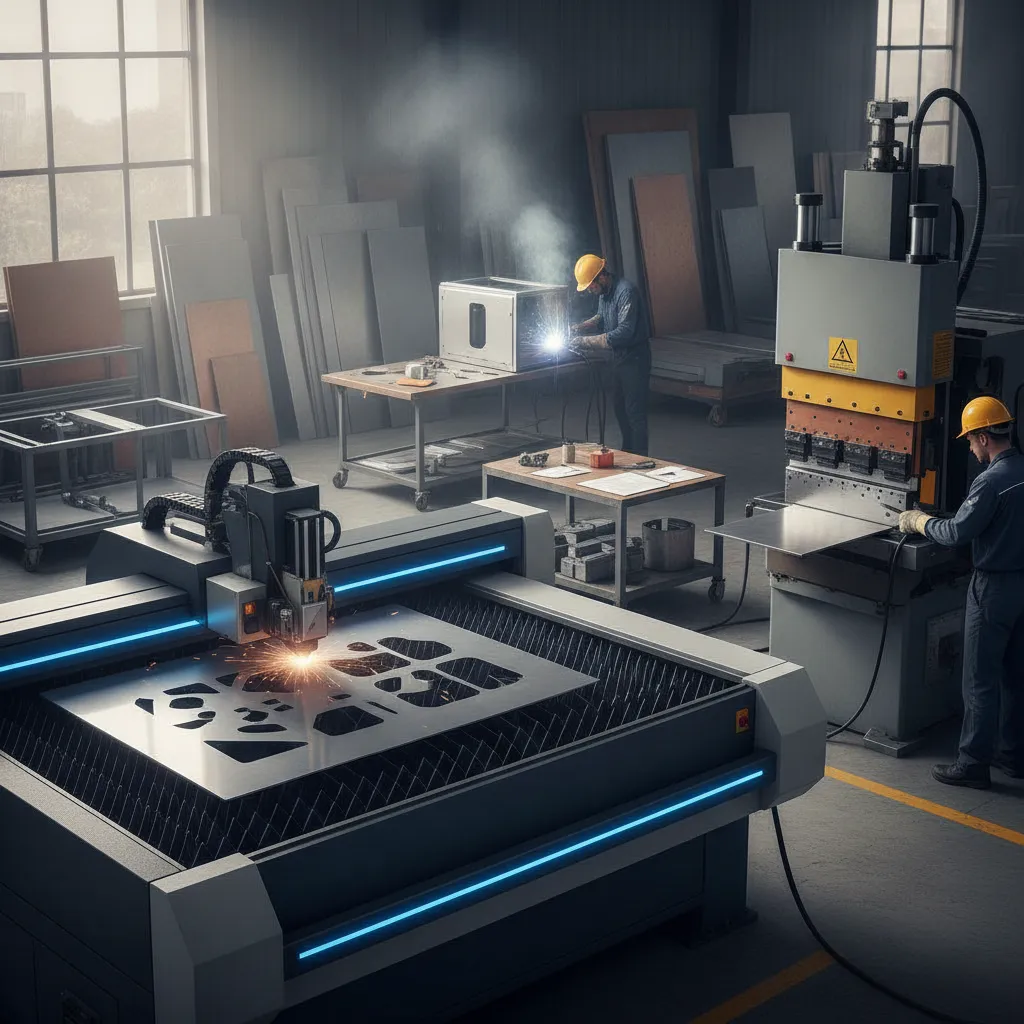
What Is the Sheet Metal Fabrication Process and How Does It Work?
The sheet metal fabrication process converts flat metal stock, typically 0.5 mm to 6 mm thick, into functional parts through cutting, forming, and joining operations.
Unlike casting or forging, which start with molten metal or solid billets, sheet metal fabrication works entirely with pre-rolled flat stock. That distinction matters: the material retains its grain structure and surface finish throughout, which keeps strength high and post-processing minimal.
“Sheet metal fabrication remains one of the most versatile manufacturing processes available — the combination of low tooling costs, fast turnaround, and material strength makes it the default choice for metal enclosures and structural brackets at low-to-mid volumes.” — Dr. Kalpakjian, Professor of Mechanical Engineering, Illinois Institute of Technology
What Are the Two Most Common Processes in Sheet Metal Fabrication?
Every sheet metal workflow runs through two process families in sequence. First come the subtractive processes, laser cutting, plasma cutting, and punching, which remove material to define the part’s 2D profile. Then come the deformation processes, bending, stamping, and roll forming, which change that profile into a 3D geometry without removing any material.
The order matters because cutting defines the blank, and forming defines the final shape. Joining operations such as welding, riveting, or hardware insertion follow once each formed component is complete.
Gauge thickness drives what each step can achieve. Laser-cut parts routinely hold tolerances of ±0.1 mm on sheet up to 3 mm thick, but thicker stock demands wider tolerances and different tooling. Selecting the wrong gauge for a given process is one of the most common causes of rework.
For a detailed visual walkthrough of how these stages connect in practice, this sheet metal fabrication process video on YouTube provides a clear step-by-step demonstration.
Is Sheet Metal Fabrication Difficult to Learn and Execute?
CAD/CAM software has significantly lowered the entry barrier, operators can program a laser cutter from a DXF file in minutes. But design-for-manufacturability (DFM) knowledge is still required to avoid expensive mistakes: a bend placed too close to a hole, for example, will distort the feature during forming.
Skilled fabricators understand how material springback, grain direction, and bend radius interact. That knowledge is what separates a part that assembles correctly the first time from one that requires three rounds of rework.
Main Steps and Techniques in the Sheet Metal Fabrication Process
A typical sheet metal fabrication process runs through four sequential stages: design and file prep, cutting, forming, and joining, each with distinct techniques and tolerances.
Stage 1, Design and File Preparation
Parts are modeled flat (unfolded) in CAD software before any material is touched. Engineers calculate bend allowances at this stage and export geometry as DXF or DWG files, which CNC cutting machines read directly. Skipping accurate bend allowance calculations here causes dimensional errors that no downstream correction can fix.
According to the Protolabs Network sheet metal fabrication design guide, the most common DFM errors submitted to fabrication shops involve incorrect bend allowances and missing tolerances on critical features — both of which are avoidable with a thorough pre-production file review.
Stage 2, Cutting Techniques: Laser, Plasma, Waterjet, and Punching Compared
Laser cutting handles complex profiles with a tolerance of ±0.1 mm and works well on sheet up to roughly 25 mm thick. Plasma cutting suits thicker stock but delivers lower edge precision, making it better for structural blanks than finished parts. Waterjet cutting introduces no heat-affected zone, critical for materials that warp or harden under thermal stress. Punching and blanking trade flexibility for speed: cycle times are fast enough to make them the default choice for high-volume, simple-geometry runs.
The key differences between cutting methods can be summarized as follows:
- Laser cutting: Best for complex profiles, tight tolerances (±0.1 mm), and sheet up to 25 mm thick.
- Plasma cutting: Suited to thicker structural stock where edge precision is less critical.
- Waterjet cutting: No heat-affected zone; ideal for heat-sensitive or exotic materials.
- Punching and blanking: Fastest cycle times; most cost-effective for high-volume, simple geometries.
- Shearing: Straight-line cuts only; used for trimming and squaring sheet stock quickly.
Stage 3, Forming Techniques
Press brake bending is the most common forming method, shaping flat blanks along a straight axis. The minimum bend radius rule applies here: keep the inside radius at 1× material thickness or greater to avoid cracking, though harder alloys like 7075 aluminum require larger radii than mild steel. Roll forming produces continuous profiles, channels, angles, tubes, by passing sheet through successive roller stations. Stamping and deep drawing produce high-volume enclosures in a single press stroke, while hemming folds an edge back on itself to eliminate sharp panel edges.
“The press brake is still the workhorse of the sheet metal shop. Understanding springback behavior for each alloy and thickness combination is what separates a first-pass success from a costly rework cycle.” — Todd Kirchoff, Senior Applications Engineer, Trumpf Inc.
How to Join Sheet Metal Parts: Welding, Fastening, and Bonding Best Practices
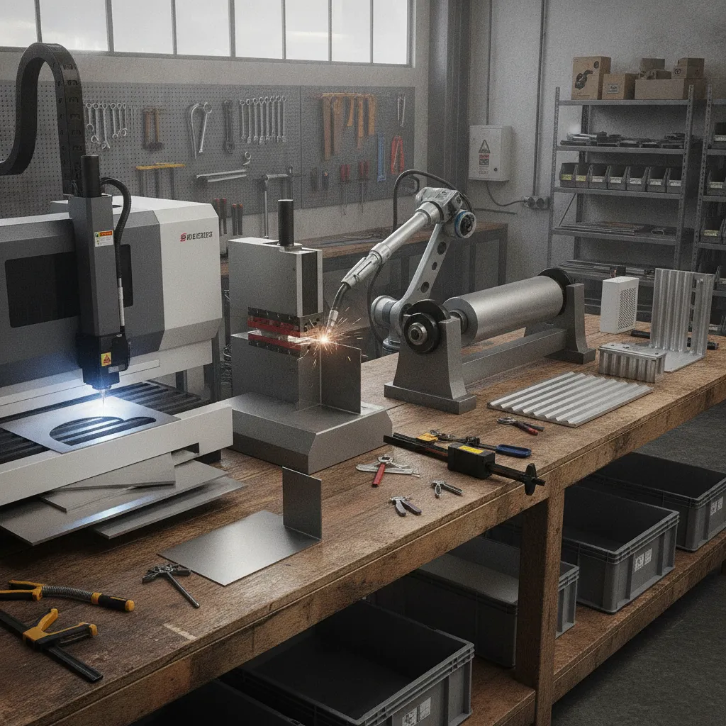
MIG welding works for most structural joints; TIG welding is slower but produces cleaner, lower-distortion beads on thin or visible surfaces. Spot welding joins thin overlapping sheets with localized resistance heat, fast and consistent for automotive-style panels. Where disassembly is required, riveting and self-clinching fasteners (PEM nuts, studs) are the standard choice because they create permanent anchor points without welding. Adhesive bonding handles mixed-material assemblies, aluminum bonded to composite, for example, where welding is not possible and mechanical fasteners would concentrate stress.
Materials and Finishes Used in Sheet Metal Fabrication
Material choice determines cost, corrosion resistance, weight, and which surface finishes are even possible, so it drives every downstream decision in the sheet metal fabrication process.
Common Sheet Metal Materials
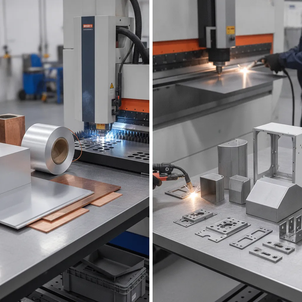
Mild steel is the default for structural and general-purpose parts: it costs less than most alternatives, welds cleanly, and machines well, but it rusts without a protective finish. Stainless steel grades 304 and 316 resist corrosion without coating, making them standard in food processing and marine environments, though material and tooling costs run higher.
Aluminum grades 5052 and 6061 offer the best weight-to-formability ratio for enclosures, brackets, and aerospace panels. Copper and brass appear where electrical conductivity or thermal transfer matters more than structural strength.
Surface Finishing Options
Powder coating bonds a durable polymer layer to steel or aluminum and supports a full color range. Anodizing applies only to aluminum, it builds a hard oxide layer that improves wear resistance and accepts dye. Electroplating adds nickel, zinc, or chrome for corrosion and wear protection on steel parts.
Brushing and bead blasting are cosmetic treatments that produce a uniform matte or satin texture. Passivation restores the natural oxide layer on stainless steel parts after machining or welding removes it.
Design Rules That Optimize Sheet Metal Fabrication
Three rules prevent the most common fabrication failures. Hole diameter must equal or exceed material thickness to avoid punch breakage. Bend-to-edge distance should be at least 3× material thickness to prevent cracking or distortion. Avoid features that force secondary setups, each additional setup adds cost and introduces alignment error.
Sheet Metal Fabrication Inspection and Quality Control
First-article inspection (FAI) validates that the initial production part matches the drawing before a full run begins. CMM measurement confirms critical dimensions on complex or tight-tolerance parts. Visual inspection references ISO 2768 tolerancing standards, while weld quality is assessed against AWS D1.1 (structural steel) or EN 1090 (structural steel and aluminum assemblies).
ISO 9001 certification is the baseline quality management requirement for most industrial customers. Aerospace sheet metal parts require AS9100 certification, which adds risk management and traceability requirements on top of the ISO 9001 framework. The American Society of Mechanical Engineers (ASME) Y14.5 standard governs dimensioning and tolerancing practices referenced in sheet metal drawings across North American industry.
How Sheet Metal Fabrication Compares to Injection Molding, CNC Machining, and 3D Printing
Sheet metal fabrication suits low-to-mid volume metal parts with tight budgets; injection molding, CNC machining, and 3D printing each win in specific scenarios.
Cost Differences: Sheet Metal Fabrication vs. Other Manufacturing Methods
Against CNC machining, sheet metal fabrication is faster and cheaper for thin-walled enclosures, brackets, and panels. CNC machining carries higher per-part setup costs at low volumes, but it wins on complex 3D geometries, tight internal tolerances, and fully solid parts where sheet metal simply cannot compete.
Injection molding demands tooling investment of $5,000–$100,000 or more before the first part ships. That cost makes sense at 10,000+ units, where per-part prices drop dramatically. Sheet metal carries far lower tooling costs and remains the better choice when you need metal-strength properties at low-to-mid volumes, think 50 to 5,000 parts.
3D printing requires zero tooling and handles complex internal geometries that no other process can match, making it the go-to for rapid prototyping. Once volumes exceed roughly 50–100 parts, the sheet metal fabrication process delivers superior strength, surface finish quality, and cost efficiency. A typical sheet metal prototype runs $50–$500 per part depending on complexity, with per-part costs dropping sharply above 500 units.
Industry Standards and Certifications That Apply to Sheet Metal Fabrication
Certification requirements often determine which process is viable, not just cost. Aerospace components require AS9100 certification; medical enclosures commonly require ISO 13485; structural steel fabrication references EN 1090 or AWS D1.1 welding standards. Most 3D printing shops do not yet hold these certifications, which disqualifies them from regulated industries regardless of geometric capability.
Buyers sourcing safety-critical parts should confirm a supplier’s active certification status before comparing quotes across processes. The NIST Manufacturing Extension Partnership (MEP) provides resources to help manufacturers identify certified fabrication suppliers and understand applicable standards.
“Certification is not a checkbox — it is a documented system that ensures every part leaving the shop meets the same standard as the first article. For regulated industries, it is non-negotiable.” — Maria Chen, Quality Systems Director, Aerospace Fabricators Association
Real-World Applications, Common Defects, and Limitations of Sheet Metal Fabrication
Sheet metal fabrication serves aerospace, automotive, electronics, HVAC, and medical device manufacturing, but it has clear limits engineers must plan around.
Aerospace manufacturers rely on the process for airframe brackets and ducting, where tight tolerances and lightweight aluminum alloys are non-negotiable. Automotive production uses it for body panels and chassis components at high volume. Electronics enclosures, server racks in particular, move from a DXF file to a powder-coated finished part in 3–5 business days using laser cutting, press brake bending, and a powder coat finish, which illustrates how fast the sheet metal fabrication process can turn around a production-ready part. HVAC contractors depend on it for ductwork and plenums, and medical device makers use formed sheet metal for equipment housings and surgical trays that must meet strict hygiene standards.
The process does have hard boundaries. Stock thicker than 12 mm is better handled by plate fabrication or forging, where the material’s cross-section demands different tooling and force. Complex 3D internal features, cavities, undercuts, internal threads, are impossible in a single formed part and require multi-piece assembly. Deep-draw parts such as canisters or cups need specialized progressive dies, which carry a significant tooling investment that only pays off at volume.
On sustainability, the sheet metal fabrication process generates scrap offcuts, but metal scrap is nearly 100% recyclable, a meaningful advantage over plastic injection molding, where mixed-polymer waste often goes to landfill. According to the U.S. Environmental Protection Agency (EPA) metals recycling data, steel and aluminum recycling rates consistently exceed 60–70%, making sheet metal fabrication one of the more environmentally responsible manufacturing choices for metal components.
Common Defects in Sheet Metal Fabrication and How to Troubleshoot Them
Four defects appear repeatedly across fabrication shops, and each has a documented fix.
- Springback in bending: Metal elastically recovers after the punch retracts, leaving the bend angle short of spec. Compensate by overbending past the target angle, or switch to a bottoming die that sets the material fully.
- Warping from welding heat: Uneven thermal expansion distorts flat panels. Use clamps to restrain the workpiece, follow a tack weld sequence that distributes heat symmetrically, or apply post-weld straightening.
- Burrs on cut edges: Laser cutting and punching both leave edge burrs that create assembly and safety problems. Add a dedicated deburring step, or adjust laser focus and feed speed to minimize burr formation at the source.
- Cracking at bends: Tight bend radii or work-hardened material cause cracks along the outer face of the bend. Increase the bend radius to at least the material thickness, or anneal the workpiece to restore ductility before forming.
Frequently Asked Questions
What thickness of metal is considered ‘sheet metal’ in fabrication?
Sheet metal typically ranges from 0.5 mm (24 gauge) to 6 mm (approximately 0.25 inches) thick. Material thinner than 0.5 mm is generally classified as foil; anything thicker than 6 mm is considered plate. The exact boundary varies by material, aluminum sheet runs up to about 6.35 mm, while steel sheet is commonly defined as under 3 mm in many fabrication standards. Always confirm the gauge range your shop supports before finalizing a design.
How long does the sheet metal fabrication process typically take from design to finished part?
Lead times range from 3 business days for simple laser-cut blanks to 4–6 weeks for complex assemblies requiring welding, hardware insertion, and multi-stage finishing. Prototype quantities (1–10 parts) move faster than production runs because they skip tooling queues. The biggest delays come from design revisions after DFM review and finish scheduling, anodizing and powder coating often add 5–7 business days. Submitting a complete, toleranced drawing on day one cuts lead time significantly.
What file formats do sheet metal fabrication shops require for quoting and production?
Most shops accept STEP (.stp/.step) or IGES files for 3D models and DXF or DWG files for flat-pattern cutting. STEP is the safest choice, it preserves bend lines, material thickness, and feature geometry across CAD platforms. Always include a 2D drawing PDF with tolerances, material callouts, and finish specifications alongside the 3D file, since model files alone rarely contain all the information a shop needs to quote accurately.
What is springback in sheet metal bending and how do fabricators account for it?
Springback is the partial elastic recovery of metal after a bending force is released, causing the bend angle to open slightly beyond the intended angle. The effect is more pronounced in high-strength materials like stainless steel and spring steel than in soft aluminum. Fabricators compensate by overbending, programming the press brake to hit a slightly tighter angle than required so the part springs back to the target. Experienced shops build material-specific springback tables into their CNC press brake programs to maintain consistent results across production runs.
What are the most important design-for-manufacturability (DFM) rules for sheet metal fabrication?
The most critical DFM rules for the sheet metal fabrication process are: keep hole diameters equal to or greater than material thickness to prevent punch breakage; maintain a bend-to-edge distance of at least 3× material thickness to avoid cracking; ensure all bend radii are consistent across the part to minimize tooling changes; and avoid features that require secondary setups, since each additional setup adds cost and introduces cumulative alignment error. Reviewing these rules before submitting files eliminates the majority of DFM rejections.
Conclusion
The sheet metal fabrication process rewards preparation. Choosing the right material before cutting begins, designing bend reliefs and consistent radii into your CAD model, and specifying finish requirements early, these three decisions eliminate the majority of costly rework and schedule delays.
Tolerances and file quality matter as much as the manufacturing steps themselves. A STEP file paired with a fully dimensioned 2D drawing gets you an accurate quote; a vague sketch gets you a phone call and a week’s delay.
As a concrete next step, pull your current part drawing and verify that every bend radius is at least equal to the material thickness, that single check resolves the most common DFM rejection before it reaches a fabricator’s desk. For further reading, the Geomiq sheet metal fabrication guide and the Protolabs Network design guide both provide detailed reference tables for tolerances, materials, and finishing options.
Recommended Articles
Explore more from our content library:
