

An automatic lathe is a self-acting machine tool that performs turning, drilling, threading, and other machining operations with minimal human intervention, using either mechanical cams or CNC controls to guide cutting tools through preset sequences. Originally developed to mass-produce threaded fasteners and small precision parts, today’s machines serve industries from automotive to medical device manufacturing. They fall into two broad families, screw machines and automatic chuckers, each suited to different part geometries and production volumes.
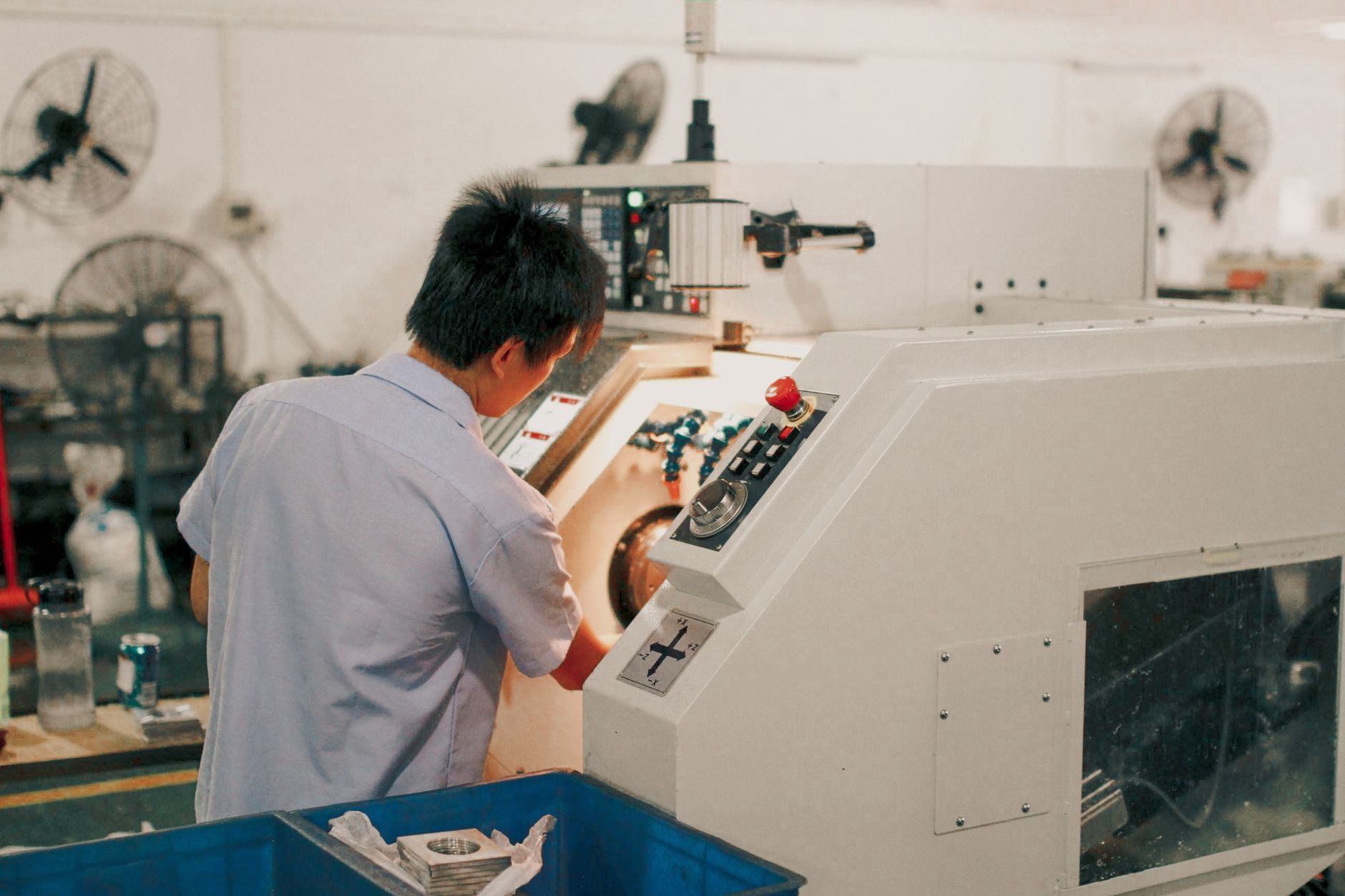
What Is an Automatic Lathe and How Does It Work?
An automatic lathe executes a full machining cycle, feeding stock, cutting, and parting off, without an operator repositioning the workpiece between steps.
That single capability separates it from a manual lathe, where a skilled operator controls every tool movement by hand. On these machines, the cycle repeats identically for every part in a production run, removing operator skill as a variable in part-to-part consistency. A trained machinist sets up the machine once; the machine does the rest.
Key Components and Design Features of an Automatic Lathe
Every machine in this category shares a common set of working elements. A bar stock feeder or chuck loads raw material into the headstock spindle, which rotates the workpiece at a controlled speed. A collet or chuck clamping system grips the bar stock precisely before cutting begins.
Cutting tools mount in a turret or cross-slide tool holders arranged around the spindle. Each tool engages the workpiece in a timed sequence, turning the outer diameter, drilling a bore, threading a profile, before a parting tool cuts the finished piece free. The cycle then resets automatically for the next part.
Two control mechanisms drive this sequence. In cam-driven mechanical systems, a rotating camshaft times every tool movement: the cam profile physically dictates when each slide advances or retracts. In CNC systems, software coordinates servo motors to achieve the same sequencing with far greater flexibility, changing a part program replaces re-cutting a cam.
A Brief History of Automatic Lathe Technology
These machines first appeared in the 1870s, driven initially by line shafts and leather belts in high-volume screw and fastener shops. Early single-spindle screw machines were mechanically controlled and built for one purpose: producing identical small parts at a rate no hand-operated lathe could match.
Multi-spindle designs followed, machining several parts simultaneously on a single machine to multiply output further. The Bullard Mult-Au-Matic, introduced in 1914, illustrated how far mechanical automation had advanced within just a few decades.
From the 1950s onward, NC and then CNC controls entered the picture, replacing fixed cams with programmable logic. Swiss-type CNC lathes, marketed by manufacturers such as DMG Mori and Tsugami as ‘automatic’, now handle the most complex small-diameter parts. The core principle of self-acting operation has not changed; only the mechanism that enforces it has.
Main Types of Automatic Lathes and How They Differ
These turning machines fall into four main categories, screw machines, automatic chuckers, Swiss-type, and multi-spindle, each suited to a distinct combination of part size, tolerance, and volume.
What Is a Screw Machine and How Does It Differ from Other Automatic Lathes?
The screw machine is the original design of this type, developed in the 1870s to mass-produce threaded fasteners from long bar stock, which is where the name comes from. Today it handles far more than screws: pins, fittings, valve stems, and similar small-diameter turned parts all run efficiently on this platform.
Single-spindle screw machines complete one part per cycle. Multi-spindle versions hold several bars simultaneously, advancing each through a different operation at the same time, so a finished part drops every cycle rather than every several cycles. That parallel processing multiplies output without requiring additional floor space.
Swiss-type automatic lathes add one critical element: a guide bushing that supports the bar stock right at the cutting point rather than at the chuck. That support eliminates deflection, which is why Swiss-type machines consistently hold tight tolerances on long, slender parts, think medical shafts and watch components, where a standard screw machine would allow the workpiece to flex.
What Is an Automatic Chucker and When Would You Use One?
An automatic chucker grips pre-cut blanks, castings, or forgings in a chuck instead of feeding bar stock. That design suits larger-diameter, shorter workpieces, flanges, gears, and pump housings, that are too wide or too short to feed from a bar.
Selecting the right machine type comes down to three variables: part diameter and length, required tolerances, and annual production volume. Small-diameter, high-volume work points toward a multi-spindle screw machine; slender precision parts point toward Swiss-type; large blanks point toward a chucker.
The table below summarizes how each type maps to common production scenarios:
- Multi-spindle screw machine: Small-diameter bar stock, very high volumes, stable part designs, minimal changeover.
- Swiss-type lathe: Long, slender parts with tight tolerances, medical and watchmaking applications, diameters typically under 32 mm.
- Single-spindle screw machine: Moderate volumes, mixed part families, straightforward turned geometries.
- Automatic chucker: Large-diameter blanks, castings or forgings, parts too short or wide for bar feeding.

Mechanical vs. CNC Automatic Lathes: Cost and Performance Compared
Mechanical automatic lathes win on raw throughput for stable, high-volume runs; CNC versions win on flexibility and shorter changeover times. You can explore modern CNC lathe options from manufacturers such as Tormach to understand how current platforms balance these tradeoffs.
What Factors Should You Consider When Choosing Between Mechanical and CNC Automatic Lathes?
Cam-driven mechanical lathes deliver their best value once the cams are ground and set. At that point, cycle times are extremely fast and the machine can run the same part reliably for months or years without intervention, making per-unit costs very low when part designs rarely change.
The mechanical lathe’s core weakness is changeover. Replacing or re-grinding cams to accommodate a new part geometry can consume hours or even days of setup time. That lost production time makes short runs or frequent design revisions expensive, not because the machine is inefficient, but because the setup cost is amortized over too few parts.
CNC automatic lathes shift that tradeoff significantly. A program change happens at a control terminal in minutes rather than days, so shorter production runs and design iterations become economically viable. The tradeoff is that a well-tuned cam machine at peak volume can still edge out a CNC lathe on raw cycle time for identical parts, the mechanical system has fewer computational steps between command and cut.
Cost-Benefit Tradeoffs of Upgrading to CNC Automation for Light Manufacturing
The practical decision comes down to break-even run length. Mechanical multi-spindle machines represent a premium capital outlay, but ongoing programming costs are negligible once cams are set, tooling amortization and operator skill are the dominant variables. CNC lathes carry a more budget-friendly entry point for single-spindle configurations, but require sustained investment in programming expertise, CAM software, and operator retraining whenever part families change.
Shops running mixed, lower-volume, or frequently revised production almost always favor CNC. Shops producing one or two stable part families in very high quantities, fasteners, hydraulic fittings, valve stems, often keep mechanical equipment running precisely because changeover cost never materializes.
Real-World Applications of Automatic Lathes Across Industries
These turning machines produce high-volume precision parts across automotive, medical, electronics, and fastener manufacturing, wherever tight tolerances and consistent output are non-negotiable.
How Automatic Lathes Are Used in Automotive and Medical Device Manufacturing
Automotive production relies on this type of equipment for transmission shafts, valve bodies, fuel system fittings, and brake components. These parts require surface finishes and dimensional tolerances that directly affect safety and assembly fit, a valve body that runs 5 microns oversize can cause hydraulic leakage at operating pressure.
Medical device manufacturing depends almost entirely on Swiss-type automatic lathes for bone screws, surgical instrument shafts, dental implant bodies, and catheter fittings. Biocompatible materials like Grade 5 titanium and 316L stainless steel machine differently from standard alloys, and guide-bushing support keeps slender workpieces stable enough to hold micron-level tolerances across thousands of identical parts.
Electronics manufacturers use multi-spindle machines to produce small-diameter brass and copper connector pins, terminals, and standoffs at volumes that single-spindle machines cannot sustain economically. A six-spindle machine cutting connector pins can complete one part per second, the only practical way to supply connector assemblies at electronics industry scale.
Fastener and hardware production remains one of the original applications for this technology. Bolts, studs, and threaded inserts are still produced on cam-driven and CNC machines at scale, making this equipment central to any precision fastener supply chain.
Latest Technology Advancements in Automatic Lathe Design
The most significant shifts in 2024–2025 involve three converging developments. In-process gauging now feeds dimensional data back to the control system in real time, allowing the machine to correct tool offsets before a part drifts out of tolerance rather than after scrap is generated.
IoT connectivity lets production teams monitor spindle load, vibration signatures, and thermal drift remotely, enabling predictive maintenance schedules that reduce unplanned downtime. Hybrid Swiss/CNC platforms combine traditional guide-bushing accuracy with full five-axis capability, so a single setup can complete complex geometries that previously required two or three separate operations. For a visual overview of how modern CNC turning centers operate, this CNC lathe demonstration video provides a useful reference.
How to Set Up, Program, and Maintain an Automatic Lathe
Setting up this type of machine correctly, from bar stock alignment to a verified dry cycle, prevents scrap, protects tooling, and keeps dimensional tolerance consistent across a full production run.
Step-by-Step Programming and Setup Guide for Beginners
Start by loading bar stock into the feeder and aligning it concentrically with the spindle centerline. Misalignment at this stage causes bar whip at speed, which compounds into surface finish problems and premature guide bushing wear.
Set collet or chuck clamping pressure according to the bar diameter and material specification, too little pressure allows slippage; too much crushes thin-walled stock. Install cutting tools in the turret, then enter tool offsets so the control knows the exact nose position of each insert.
Load or enter the part program next. On CNC machines, turning operations use structured G-code: G96 maintains constant surface speed as diameter changes, G75 runs grooving cycles, and G76 automates multi-pass threading. Most modern controls also offer conversational programming interfaces that translate part geometry, diameter, length, thread pitch, directly into G-code without requiring the operator to write a single line manually.
On mechanical automatic lathes, cam profiles replace G-code entirely. Each cam’s lead angle determines the feed rate for its corresponding tool, and the timing relationship between cams controls the sequence of cuts. Document every cam configuration, disc position, follower preload, and timing marks, so repeat jobs can be set up quickly without re-engineering from scratch.
Before committing to a full run, execute a single-part dry cycle with the coolant on and the feed rate reduced. Measure the first part against the drawing before releasing the machine to run unattended.
Common Automatic Lathe Problems and How to Troubleshoot Them
Three failure modes account for the majority of quality escapes on automatic lathes: chatter, bar whip, and inconsistent part length.
- Chatter produces a visible, repeating wave pattern on the machined surface. Root causes include worn spindle bearings, excessive tool overhang beyond roughly 3× the insert width, or cutting speed that excites the natural frequency of the setup. Reduce overhang first, it’s the fastest fix, then check bearing preload if chatter persists.
- Bar stock whip occurs when spindle speed is too high for the unsupported bar length or diameter. Add steady-rest support or reduce RPM until the bar runs without vibration. Left unchecked, whip accelerates guide bushing wear and can damage the feeder finger mechanism.
- Inconsistent part length usually traces to bar feeder finger wear or collet contamination from chips or coolant residue. Inspect the feeder fingers for deformation and clean the collet bore at each setup changeover.
A consistent maintenance schedule prevents these issues from compounding. Lubricate spindle bearings at the intervals the machine builder specifies, typically every 500 to 2,000 operating hours depending on bearing type, because heat from under-lubricated bearings causes thermal growth that shifts part diameter. Inspect collets and guide bushings for wear weekly on high-volume jobs; even 0.01 mm of bushing clearance translates directly into runout on the finished part. Change coolant filtration media on a fixed schedule to prevent swarf from recirculating and scoring the guide bushing bore. On mechanical lathes, check cam follower condition at each job changeover, a flat spot on a follower produces a repeating dimensional error that looks like a programming mistake but is purely mechanical.
Frequently Asked Questions
What is the difference between a Swiss-type automatic lathe and a standard automatic lathe?
A Swiss-type automatic lathe feeds the workpiece through a guide bushing, supporting it close to the cutting tool, which makes it far better suited to long, slender parts than a standard this strategy. Standard automatics hold the bar stock in a fixed chuck or collet and move the tooling, so rigidity drops as part length increases. Swiss-type machines dominate medical, watchmaking, and electronics applications where diameters under 32 mm and tight tolerances are the norm. Some manufacturers, including Tsugami, market CNC Swiss-type machines explicitly as “this approachs”.
Can an automatic lathe work with materials other than metal?
Yes, these machines can process plastics, composites, and even wood, though they are most commonly used for metal bar stock. Materials such as PTFE, nylon, Delrin, and brass-filled polymers run well on both cam-driven and CNC the practices. Cutting parameters, speed, feed, and coolant, must be adjusted for each material to prevent heat buildup or tool damage.
How long does it take to set up an automatic lathe for a new part?
Setup time varies widely: a cam-driven this practice can take several hours to a full shift to configure for a new part, while a CNC this method typically requires 30 minutes to 2 hours depending on tooling changes and program complexity. Cam changes on mechanical machines are the dominant time cost. CNC machines reduce changeover time significantly because a saved program can be reloaded quickly for repeat orders.
What operator skills are needed to run a CNC automatic lathe?
Operators need proficiency in CNC control interfaces, the ability to read engineering drawings and tolerances, and hands-on experience with tool offsets and work-holding setup. Knowledge of G-code is helpful but not always required, as many modern controls use conversational programming. For Swiss-type CNC automatics, understanding guide bushing clearance and bar-feed systems adds an extra layer of required competence.
What is the typical production output of an automatic lathe compared to a manual lathe?
Output depends heavily on part complexity and machine configuration, but this strategys routinely achieve cycle times measured in seconds per part, whereas a manual lathe requires an operator to reposition and control tooling at every step. Multi-spindle configurations multiply that advantage further by completing one finished part per cycle across several simultaneous operations. For stable, high-volume part families, the productivity difference between automated and manual turning is substantial enough that manual operation is rarely economical at scale.
Conclusion
The this approach remains one of manufacturing’s most productive tools for high-volume, tight-tolerance turned parts, but only when matched correctly to the job. Three things matter most: choosing between cam-driven and CNC control based on your volume and changeover frequency; selecting Swiss-type versus standard configuration based on part length-to-diameter ratio; and specifying surface finishing requirements before the first part runs, not after.
If you are sourcing turned components rather than running your own machines, review your current part drawings against these criteria and request a process audit from your precision machining supplier, it is the fastest way to identify where cycle time or scrap rate can be cut.
Recommended Articles
Explore more from our content library:
