
CNC machining tolerance is the allowable deviation between a part’s specified dimension and what the machine actually produces, usually expressed as a plus/minus value like ±0.005 inches. It matters because every machining process has natural variation from tool wear, material behavior, and thermal changes, and the tolerance you specify determines whether mating parts fit, whether the part functions as designed, and how much the job costs to produce. Tighter tolerances demand slower cuts, more inspection, and pricier equipment, so matching tolerance to actual functional need, not defaulting to the tightest number, is the real skill.

What Is CNC Machining Tolerance and Why Does It Matter?
A tolerance is a range, not a single number: a dimension specified as 1.000 inch with a tolerance of ±0.002 inch means anything from 0.998 to 1.002 inch is an acceptable part. No CNC process cuts to one exact figure every time. Tool wear, material spring-back, vibration, and heat buildup all push the actual dimension around a nominal target, so the print has to state how far off that target a part can land and still work.
This is the practical core of CNC machining tolerance: it sets the boundaries within which normal process variation is fine, and outside of which the part gets rejected. For a deeper technical breakdown of how these ranges are calculated and applied, see this guide to fine-tuning tolerances for CNC machined parts.
What Are the Four Main Types of Tolerances Used in CNC Machining?
Shops typically manage four distinct tolerance categories, and mixing them up is a common source of drawing errors.
- Linear/dimensional tolerance, controls length, width, depth, or diameter. Example: a shaft specified at 10mm ±0.05mm.
- Geometric tolerance, controls form and position, such as flatness, roundness, or perpendicularity, independent of size. A bolt pattern needs its holes positioned relative to each other, not just sized correctly.
- Angular tolerance, controls angles between faces or features, like a 45-degree chamfer held to ±0.5 degrees.
- Surface finish tolerance, controls texture, measured in microinches or micrometers Ra. A sealing surface needs a smoother finish than a structural bracket.
Is ±0.001 Inch a Tight Tolerance, and What Does That Mean for Your Application?
Yes, ±0.001 inch (0.025mm) sits well inside precision territory, while standard commercial machining typically runs closer to ±0.005 inch. That fivefold gap changes how the part gets made, and it’s one of the first questions any CNC machining tolerance discussion should settle before quoting a job.
Holding ±0.001 inch generally means slower feed rates, more frequent tool changes to counter wear, temperature-controlled shop conditions, and inspection with calipers or gauges rather than a quick visual check. Each of those steps adds machine time and labor, which is why tighter tolerance almost always raises cost.
The function side matters just as much. A bearing bore machined outside its tolerance band can bind against the shaft it houses, or run loose enough to wobble and wear out prematurely, a failure traced directly back to a tolerance call made at the design stage, not a machining mistake on the shop floor.
How Do You Specify Tolerances in CAD Design Files and Drawings?
You set a title-block default tolerance for general dimensions, then add specific callouts only on features where fit or function demands more control.
Every machining drawing carries a default tolerance in the title block, usually expressed as a plus/minus value tied to decimal places (a two-place dimension might default to ±0.010 in, a three-place to ±0.005 in). That default applies to every dimension on the print unless you override it. Critical features get individual callouts instead: a bore that houses a bearing, a flange face that seals against a gasket, a hole pattern that has to align with a mating part. Mixing these two levels correctly is the entire discipline of CNC machining tolerance specification, most drawings should have a loose default and a short list of tight, purposeful exceptions. This guide to CNC machining tolerances covers common default values by feature type in more detail.
What GD&T Symbols and Callout Methods Should You Use When Specifying Tolerances?
Geometric Dimensioning and Tolerancing (GD&T) controls shape, orientation, and location in ways a plus/minus number cannot touch. A linear tolerance on a shaft diameter says nothing about whether that shaft is straight or bowed. Common GD&T controls relevant to CNC machining tolerance include:
- Flatness, controls surface distortion on a sealing face.
- Position, controls how far a hole’s actual center can drift from its theoretical location, which matters more for assembly than the hole’s diameter alone.
- Concentricity and runout, control how true a rotating feature spins relative to a datum axis, important on shafts, pulleys, and anything spinning near a bearing.
- Datums, establish the reference points everything else measures from; picking the wrong datum scheme is a common source of parts that measure “in tolerance” feature by feature but still won’t assemble.
What Common Mistakes Do Engineers Make When Over-Specifying or Under-Specifying Tolerances?
Over-specification means marking every dimension tight “to be safe,” which forces the shop to inspect and machine every feature at high precision even where it has no effect on function, inflating cost without improving the part. Under-specification is the opposite failure: leaving a bearing bore or mating fit at the loose default tolerance, which looks fine on paper until final assembly reveals a part that won’t press together. Both mistakes trace back to skipping the step of asking which features actually mate, seal, or bear load.
What Tolerance Levels Can Different Materials Actually Achieve?
Material choice sets the ceiling on CNC machining tolerance before a cutting tool ever touches the workpiece, hardness, thermal behavior, and machinability all play a role.
Hardness determines how much a tool deflects under cutting force; softer materials let the tool push in slightly, while harder materials resist and hold their shape better. Thermal expansion coefficient matters because cutting generates heat, and a material that expands more during machining will shrink back differently once it cools, shifting final dimensions. Machinability rating, a rough measure of how predictably a material cuts, rolls both factors together into a practical sense of how consistent a shop’s results will be.
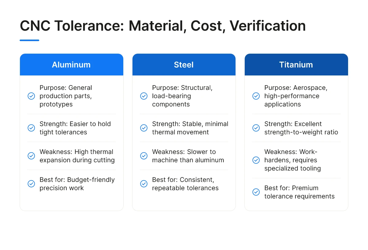
How Do Aluminum, Steel, and Titanium Differ in Their Achievable Tolerance Ranges?
Aluminum generally accepts tighter tolerances with less effort because it cuts fast and cool, but it also moves more during machining due to a higher thermal expansion rate, so parts can shift slightly as they cool from cutting temperature. Steel is more dimensionally stable once machined but cuts slower, meaning more time under the tool and more opportunity for tool wear to creep into the dimension. Titanium sits at the difficult end, it work-hardens where the tool contacts it, generates concentrated heat because it doesn’t conduct heat away well, and requires specialized tooling and slower feeds to avoid dimensional drift and tool damage.
Why Does Material Selection Impact the Tolerances You Can Realistically Hold?
Even a dimensionally stable material can miss tight tolerances if the part geometry works against it. Thin walls or tall, narrow features in softer materials flex under cutting force or clamping pressure, springing back slightly once released, widening the realistic CNC machining tolerance regardless of how precise the material itself is capable of being. Matching tolerance ambition to material choice at the design stage avoids costly redesign after a first article inspection fails. Surface finish specs compound this: a finer finish usually demands tighter dimensional control in the same feature, since achieving a smooth surface and holding a tight dimension often rely on the same slow, controlled cutting passes.
How Much Does Tolerance Precision Cost, and When Is It Worth It?
Tightening a CNC machining tolerance raises cost by slowing every step of production, from cutting speed to final inspection, not just by requiring a better machine.
What Is the Cost Difference Between Tight and Loose Tolerances in Production?
Four mechanisms drive the cost up as a spec tightens:
- Slower feed and speed rates, because aggressive cutting generates heat and vibration that push dimensions out of range.
- More frequent tool changes, since a dulling tool drifts before it breaks, and drift is what kills a tight tolerance.
- Extra finishing passes, a roughing cut followed by one or two light finishing cuts, to remove the material a single aggressive pass would leave inconsistent.
- Longer inspection time, since a shop floor caliper check is no longer enough, and parts may need a coordinate measuring machine and a documented inspection report.
Stacked together, these four factors explain why moving from a standard shop tolerance to a tight aerospace-grade spec shifts a job from budget-friendly to premium territory. The jump isn’t one line item, it’s slower cycle time, more tooling wear, more operator attention, and more paperwork, all compounding on the same part.
When Should You Tighten Tolerances Versus Accepting Looser Specifications to Reduce Costs?
Tighten tolerance only where it affects fit, function, or a regulatory requirement, everywhere else, looser specs save money without costing performance. A bearing seat that must press-fit within microns deserves a tight callout. A mounting hole for a general-purpose fastener on the same bracket rarely needs that same precision; a standard tolerance leaves enough clearance for the bolt to seat properly.
Scrap rate and rework risk deserve equal weight alongside machine time. As tolerance windows narrow, more parts fall outside spec during normal process variation, and rework or scrap costs stack on top of the slower cycle time already built into the price. A tolerance decision that ignores this risk undercounts the real cost of going tight.
How Do You Verify and Inspect Tolerances to Ensure Parts Meet Specifications?
Verifying CNC machining tolerance means matching the inspection tool to the tolerance grade, then checking parts at the start, middle, and end of a production run, not just at final sign-off.
What Measurement Equipment Do You Need to Verify Different Tolerance Levels?
Calipers and micrometers handle general dimensions in the +/- 0.005 in. range, the kind of tolerance common on non-critical features. Gauge pins and thread gauges confirm fits, a hole that needs to accept a dowel or a bolt within a specific clearance class needs a go/no-go pin, not a caliper reading.
For tighter or geometrically complex tolerances, true position, flatness, concentricity, a coordinate measuring machine (CMM) is the right tool. CMMs use a probe to capture thousands of data points and compare them against the CAD model, catching errors that a handheld tool would miss entirely.
First-article inspection matters as much as the equipment choice. Checking the first part off the machine against the print, before running the rest of the batch, catches a wrong offset or a misread blueprint before it becomes 200 scrap parts. In-process checks every 10 or 25 parts catch slower drift.
What Real-World Tolerance Failures or Lessons Learned Should Inform Your Design Decisions?
Tool wear and thermal expansion cause parts to drift out of tolerance during a long run even when the CNC program never changes. A cutting tool that’s sharp at part 1 is measurably duller by part 300, and a machine spindle running for six hours generates heat that expands the workpiece by a few tenths, enough to fail a tight tolerance.
A common failure pattern: a part measures in spec at the machine but fails at assembly. Often the part was measured at shop temperature with a caliper against a tolerance grade that called for micrometer or CMM verification, or measured before it cooled to room temperature. Using a caliper to confirm a tenth-thousandth tolerance gives false confidence, the instrument’s own resolution can’t reliably detect the error you’re trying to catch.
Build inspection plans around tolerance grade, not habit: loose tolerances get calipers, fits get gauges, and anything under a couple thousandths gets a CMM or comparable optical measurement.

Frequently Asked Questions
What is the standard tolerance for CNC machining if none is specified on the drawing?
Most shops default to a general tolerance around ±0.005 in (0.13 mm) for standard machining, tightening to ±0.002 in (0.051 mm) for precision work. Without a callout, the machinist applies house standards or ISO 2768 medium/fine classes, which can vary between suppliers. Unspecified tolerances create risk, always confirm the shop’s default CNC machining tolerance in writing before production runs.
Can every CNC shop hold the same tight tolerances?
No, tight tolerances depend on machine condition, tooling, metrology equipment, and operator skill, so capability varies widely between shops. A shop advertising ±0.0005 in typically needs calibrated CMMs, temperature-controlled floors, and rigid machines, not every facility invests in that setup.
Does part size affect how tight a tolerance can realistically be held?
Yes, larger parts are harder to hold to tight tolerances because thermal expansion, fixturing deflection, and machine travel errors compound over longer dimensions. A ±0.001 in tolerance on a 1-inch feature is routine; the same tolerance across a 24-inch span demands tighter environmental control and often costs more to verify.
How do tolerances differ between CNC milling and CNC turning?
Turning generally holds tighter tolerances on diameters and roundness because the part rotates against a fixed tool, reducing certain error sources present in milling. Milling involves more axis movement and tool changes, which introduces more variables affecting flatness and position. Both processes can achieve precision-grade tolerances, but the achievable limits depend on the specific feature, fixturing, and tool path involved.
How should CNC machining tolerance be communicated when working with an outside supplier?
Put the full tolerance scheme, title-block default plus any GD&T callouts, directly on the drawing rather than relying on verbal instructions or email notes. Confirm the supplier’s measurement equipment matches your tightest callout before the job starts, and ask for a first-article inspection report. Clear, written CNC machining tolerance requirements prevent disputes over parts that measure differently on each side.
Conclusion
Tolerance decisions come down to three things: specify only what the function requires, expect cost to rise sharply below ±0.001 in, and confirm your shop’s actual capability rather than assuming a catalog number applies to your part geometry. Over-tolerancing a drawing is one of the most common, and avoidable, sources of inflated machining quotes. Before your next design freeze, walk through each dimension with your machinist and mark which tolerances are critical-to-function versus cosmetic; that single review often trims cost without touching part performance.
Recommended Articles
Explore more from our content library:
