

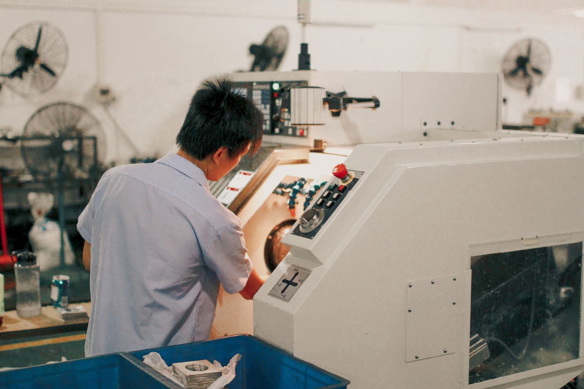
Precision tolerance manufacturing is the production of parts within tightly specified dimensional limits, the allowable deviation from a nominal measurement, using processes like CNC machining, grinding, and EDM. It matters because even small deviations can cause assemblies to bind, leak, or fail prematurely. In industries like aerospace, medical devices, and automotive, tight tolerances ensure parts are interchangeable, safe, and function consistently across every unit produced, which is why tolerance control is treated as a core engineering requirement rather than an afterthought.
What Is Precision Tolerance Manufacturing and Why Does It Matter?
Precision tolerance manufacturing means treating dimensional variation as a controlled engineering variable, not an accident, on every part that leaves the shop floor.
What is the difference between tolerance, precision, and accuracy in machining?
Tolerance is the permissible range around a nominal dimension, a shaft specified at 10 mm might carry a tolerance of ±0.01 mm, meaning anything between 9.99 mm and 10.01 mm passes inspection. Precision and accuracy are related but distinct concepts that describe how a machine actually performs against that spec. This is particularly relevant for precision tolerance manufacturing.
Precision measures repeatability: how consistently a process reproduces the same dimension across a batch. Accuracy measures how close that dimension lands to the true target value. A CNC lathe can be highly precise but inaccurate, imagine it cutting every shaft in a 500-unit run to exactly 10.03 mm. The parts are consistent with each other, but every one sits outside the ±0.01 mm tolerance band. Manufacturers need both qualities together: precision without accuracy produces reliably wrong parts, and accuracy without precision produces a scattershot of hits and misses.
Why is tight tolerance manufacturing business-critical across industries?
Out-of-tolerance parts fail in predictable, mechanical ways once they reach assembly. A shaft machined slightly oversized creates an interference fit that binds instead of rotating freely; a housing machined slightly undersized leaves a gap that lets fluid or gas leak past a seal; two mating brackets machined to different actual dimensions bolt together misaligned, transferring stress to fasteners that were never designed to carry it.
These failures rarely stay contained to one part. In regulated sectors like aerospace and medical devices, dimensional nonconformance can trigger compliance failures, recalls, and liability exposure that dwarfs the cost of the original component. Tight tolerance control also enables interchangeability, a bracket machined this quarter needs to fit the same way as one machined two years ago by a different supplier, without hand-fitting on the assembly line. That’s why tolerance control sits with engineering leadership as a core requirement, not a machinist’s afterthought.
What Are the Standard Tolerance Levels, and How Do You Choose the Right One?
Tolerance levels range from general commercial machining down to ultra-precision work measured in microns, and the right level in precision tolerance manufacturing depends on part function, not on chasing the smallest number available.
Is 0.05 mm a good tolerance, and what standards apply to different industries?
A tolerance of 0.05 mm (about 0.002 in.) sounds tight compared to standard commercial work, but its real meaning depends on the part it’s applied to. On a 10 mm bracket hole, 0.05 mm is a meaningful percentage of the feature size and may demand precision grinding or fine boring. On a 500 mm housing, that same 0.05 mm is comparatively loose relative to overall part scale and might sit within reach of standard CNC milling.
This is why engineers lean on ISO tolerance grades (IT grades) rather than judging a number in isolation. IT grades standardize acceptable variation for holes, shafts, and general dimensions across a size range, so a shop and a customer can agree on what “IT7” or “IT9” means without re-deriving it from scratch for every drawing. Protolabs, for reference, lists a standard production tolerance around ±0.13 mm and a tighter precision option near ±0.05 mm on select features.
How do ISO, GD&T, aerospace, medical, and automotive tolerance standards differ?
ISO grades cover linear size, but Geometric Dimensioning and Tolerancing (GD&T) controls form, orientation, and location, flatness, concentricity, true position, which removes ambiguity that a plus-or-minus dimension alone can’t resolve. A shaft can be within its diameter tolerance and still fail to assemble if it’s bowed or off-axis; GD&T callouts catch that. When considering precision tolerance manufacturing, this point stands out.
Industry standards then layer stricter requirements on top, driven by safety and regulatory oversight rather than preference. Aerospace and medical parts typically carry tighter tolerances and heavier documentation, including material certifications and full inspection reports, because failure modes are safety-critical. Automotive tolerances vary more by component role, a structural bracket differs from a fuel-system part.
The practical framework: match tolerance tightness to the actual functional requirement, fit, load path, sealing surface, instead of defaulting to the tightest spec available, which only adds cost without adding value.

How Do Manufacturing Processes Compare in Their Tolerance Capabilities?
CNC machining, grinding, EDM, and 3D printing each hold different tolerance ranges, and matching the process to the part matters more than chasing the tightest number available.
What tolerance capabilities does CNC machining offer compared to grinding, EDM, and 3D printing?
Standard CNC machining typically holds tolerances in the range of a few thousandths of an inch, with tighter classes available on request for critical features. Grinding goes further because it removes material in much smaller increments than a cutting tool, which lets it produce tighter, smoother surfaces on hardened metals that would chip or deflect a standard end mill. That’s why hardened shafts, bearing races, and gauge blocks often move from a mill or lathe to a grinder for the final finishing pass.
EDM works differently, it erodes material with electrical discharges instead of cutting it, so it can hold tight tolerances on hardened tool steel, carbide, and geometries with sharp internal corners or narrow slots that a rotating cutter simply cannot reach. The tradeoff is speed and cost: EDM removes material slowly, so it’s reserved for features where no other process will work, not for bulk material removal.
3D printing sits at the other end of the spectrum. Layer-by-layer deposition leaves as-printed tolerances noticeably looser than any subtractive method, so shops commonly print a near-net shape and then machine the critical mating surfaces, bores, or threads afterward to bring those specific features into precision tolerance manufacturing range.
Is there such a thing as zero-tolerance machining, and what are the practical limits?
No, every manufacturing process produces measurable variation, so “zero tolerance” is a marketing phrase, not an achievable physical state. The real engineering question is how small that variation can be made and at what cost, since tolerances near the ten-thousandth of an inch require slower cycles, temperature-controlled rooms, and more inspection time. For those exploring precision tolerance manufacturing, this matters.
As a rough guide: CNC machining suits prototyping and mid-volume production, grinding suits hardened precision components, EDM suits complex or hardened geometries standard tools can’t reach, and 3D printing suits rapid prototyping or geometries later refined by machining.
What Are the Real Costs and Tradeoffs of Achieving Tight Tolerances?
Every step tighter in a tolerance band multiplies cost through slower cuts, more tool changes, added inspection, and higher scrap rates, not through some flat markup. Precision tolerance manufacturing is a series of compounding decisions, not a single spec on a drawing.
Holding a tolerance of ±0.0005 in. rather than ±0.005 in. means the machine runs slower to limit vibration and heat, cutting tools wear faster and get swapped more often, and every part may need dimensional checks instead of sampling. Modus Advanced frames tight tolerance work as requiring specialized processes and rigorous quality control systems layered on top of standard machining. Scrap and rework also climb, a part that drifts 0.001 in. outside a loose band is a non-issue, but the same drift on a tight-tolerance surface is a reject.
What is a reasonable tolerance for machining when balancing cost and precision?
Treat tolerance as a tiered budget decision, not a uniform standard applied to every feature on a part.
- Budget-friendly: ±0.005 in. or looser for non-mating surfaces, cosmetic features, and mounting holes where fit isn’t critical.
- Mid-range: around ±0.002 in. for standard fits, bearing bores, and features that mate with other components.
- Premium/tight: ±0.0005 in. or tighter, reserved for sealing surfaces, sensor mounts, or aerospace interfaces where function fails outside spec.
Specifying premium tolerances across an entire drawing when only two features need them is the single most common source of inflated machining quotes.
How do material properties and environmental controls affect tolerance requirements and costs?
Material behavior and shop environment can undo a tight tolerance even when the machine itself is capable of holding it.
Thermal expansion means aluminum parts machined at 75°F can shrink measurably as they cool, and internal stresses from prior rolling or forging can relieve themselves after machining, warping a part hours later. Machinability varies too, free-machining alloys hold tight bands more easily than gummy or work-hardening materials. Once tolerances tighten past roughly ±0.001 in., temperature-stable rooms, humidity control, and vibration isolation stop being optional; skipping them produces parts that measure in spec at the machine but drift out of spec on the inspection table. This directly impacts precision tolerance manufacturing outcomes.
How Do You Prevent Tolerance Stack-Up in Complex Assemblies?
Tolerance stack-up happens when individual part tolerances combine across an assembly and the cumulative variation exceeds what the design can tolerate, even though every single part measures within spec. A shaft, bearing, and housing can each pass inspection alone and still jam together because their small deviations pointed the same direction.
What is tolerance stack-up analysis, and how do you design assemblies with multiple tight-tolerance components?
Engineers model stack-up before cutting metal, using two main approaches. Worst-case analysis adds up the maximum possible deviation of every dimension in a chain, guaranteeing the assembly works even in the least favorable combination, but it often demands tolerances tighter than production needs. Statistical analysis, commonly called root-sum-square (RSS), treats each tolerance as a probability distribution and calculates the likely combined variation, which is almost always smaller than the worst case. RSS lets designers reserve tight, costly tolerances for the dimensions that actually control fit or function and relax everything else, a distinction central to precision tolerance manufacturing planning on multi-part assemblies.
Beyond the math, practical design choices matter. Reducing the number of mating features in a stack shortens the chain and limits how many variations can compound. Consistent datum structures across parts stop measurement errors from multiplying between drawings. Calling out critical-to-function dimensions explicitly on the print tells the shop floor and inspection team exactly where precision cannot slip.
What emerging technologies like AI-driven quality control and automated metrology are transforming precision manufacturing?
Coordinate measuring machines and optical scanners now feed data continuously during production instead of only at final sampling, and software flags drift the moment a dimension trends toward its limit rather than after a batch ships. This shift from end-of-line sampling to in-process monitoring catches a shifting fixture or wearing tool before it produces an out-of-tolerance part, not after.
The rigor required scales with the application. Aerospace and medical assemblies typically demand documented stack-up analysis and full inspection traceability for every mating feature, while general industrial assemblies can often rely on statistical sampling and looser paper trails.

Frequently Asked Questions
What is the difference between tolerance and accuracy in manufacturing?
Tolerance is the allowable range of variation printed on a drawing; accuracy is how close the finished part actually measures to the target value. A part can be accurate but out of tolerance if the drawing’s window is narrower than the process can hold, or in tolerance but not perfectly accurate to the nominal dimension. Precision refers to how repeatable those measurements are across a production run.
How much more does tight tolerance machining cost compared to standard tolerance work?
Tight tolerance work generally costs more because slower cutting speeds, added inspection, and higher scrap risk all add labor and machine time. There’s no fixed multiplier, the increase depends on the tolerance band, material, and part geometry. Budget-friendly standard tolerances stay commodity-priced; premium micron-level tolerances shift a job into specialized, higher-cost territory. This is particularly relevant for precision tolerance manufacturing.
What tolerance can you realistically expect from 3D printed parts?
Most 3D printing processes hold tolerances in the range of a few tenths of a millimeter, looser than CNC machining. FDM and SLA parts typically need secondary machining on critical features if a drawing calls for tolerances tighter than roughly ±0.1mm, since layer-based processes introduce dimensional variation that additive alone can’t correct.
Which industries typically require the tightest manufacturing tolerances?
Aerospace, medical device, and semiconductor/optics manufacturing consistently demand the tightest tolerances because component failure carries safety or performance consequences. Automotive fuel systems and precision instrumentation also require tight control, though usually with somewhat wider bands than aerospace or implantable medical components.
How does GD&T differ from a basic tolerance callout on a drawing?
A basic tolerance callout controls only size; GD&T (Geometric Dimensioning and Tolerancing) controls form, orientation, location, and runout relative to specified datums. GD&T lets an engineer define how a hole must align to a reference surface, not just how big it can be, which matters once parts assemble against mating components.
Conclusion
Holding tight tolerances isn’t about buying the most expensive machine, it’s about matching process, material, and inspection method to what the part actually needs. Overspecifying tolerances drives up cost without improving function; underspecifying them risks assembly failures downstream. Before finalizing a drawing, flag which dimensions are truly critical and which can loosen to standard tolerances, then confirm your shop’s measured process capability against that spec rather
Recommended Articles
Explore more from our content library:
